
机械手外文翻译【骄阳书屋】
24页
1、本科毕业设计(论文)外文翻译(附外文原文) 学 院: 机械与控制工程学院 课题名称: 搬运机械手的结构和液压系统设计 专业(方向): 机械设计制造及其自动化(机械装备) 班 级: 学 生: 指导教师: 日 期: 2015年3月10日 教学fProceedings of the 33rd Chinese Control ConferenceJuly 28-30, 2014, Nanjing, ChinaThe Remote Control System of the ManipulatorSUN Hua, ZHANG Yan, XUE Jingjing , WU ZongkaiCollege of Automation, Harbin Engineering University, Harbin 15000E-mail: Abstract: A remote control system of the 5 degree of freedom manipulator was designed. This manipulator was installed into our mobile r
2、obot to constitute a remote rescue robot. The Denavit-Hartenberg method was used to establish the kinematic models and the path planning of the manipulator was researched. The operator could remote control the manipulator by the interactive interface of PC which could display moving picture and various data of the manipulator. The servos of the manipulator were controlled by the slave FPGA controller. In addition, the slave FPGA controller communicated with the PC via the wireless communication
3、module. Owing to the embedded Nios II program and IP (Intellectual Property) core generating PWM waves in FPGA, the system could control the multiple servos fast and flexible. In order to achieve real-time operation and simulation, the interactive interface was established by the mixed programming of VC and MATLAB.Key Words: The manipulator; Remote control; Denavit-Hartenberg; FPGA; Human-computer interaction1 IntroductionWith the development of the microelectronic technique and the computer tec
4、hnology, the manipulator has become essential equipment in the manufacturing industry. As we all known, the manipulator is usually applied to accomplish dull, onerous and repeated physical work, especially used to substitute the manual operation under the dangerous and the hazardous environment such as the corrosion and the high temperature.In this paper, the manipulator was installed our mobile robot. The tele-operation system of this manipulator was designed. The whole system is onstituted by
《机械手外文翻译【骄阳书屋】》由会员枫**分享,可在线阅读,更多相关《机械手外文翻译【骄阳书屋】》请在金锄头文库上搜索。
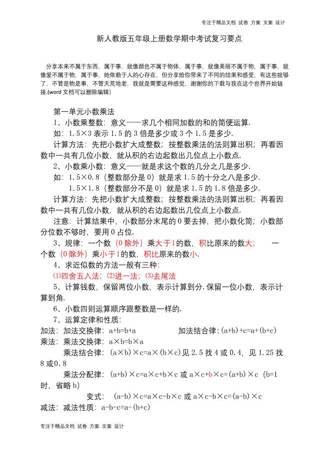
新人教版五年级上册数学期中考试复习要点.docx
2023年园艺园林学院防艾宣传活动总结.docx
关于T商业银行的服务运营模式

2023年农民工培训工作方案 4.doc
2023年XX县科技局年度党建工作计划新编.docx
选修课程策划方案
2023活动计划1257范文.docx
授之以渔循序渐进完成作文.doc
街道社区拉网式执法检查计划与街道社区消防工作计划汇编

大连理工大学21秋《起重机金属结构》在线作业三满分答案24
2023年论房地产企业应增强法制意识履行社会责任.docx
碱金属腐蚀分析
XX土地买卖居间合同范本_1
2023年销售经理年终工作总结范文(2篇).doc
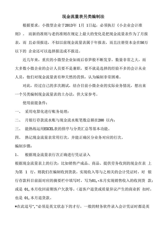
现金流量表另类编制法
2023年高中入学自我介绍范文.docx
2023年团圆的节日作文.docx
2023年学生会纪检部工作计划.docx

2023年全市土地管理工作意见.docx
2023年白血病爱心募捐倡议书.docx
 公路工程监理规范【项目材料】
2023-11-22 47页
危险废物收集转移项目资金申请报告写作模板-定制代写
2023-08-13 88页
指纹门禁机项目建议书写作模板
2023-07-21 63页
滚珠丝杠项目可行性研究报告模板立项审批
2023-01-05 87页
保险公司风险排查管理规定【劲松书屋】
2023-04-21 6页
多层加油管项目可行性研究报告-用于立项备案
2024-02-22 104页
ZP37B旋转式压片机清洁标准规程
2024-06-03 3页
激光喷码机清洁标准规程
2024-06-03 2页
奇卡诺激光喷码机清洁标准规程
2024-06-03 2页
灯检机清洁标准规程
2024-06-03 2页